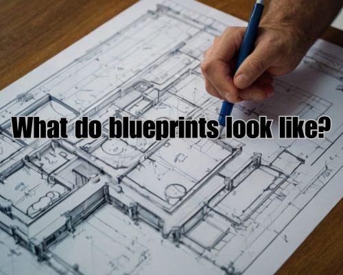
Leona Rodriguesi founder of Mornington Cabinet Makers has tp say “Blueprints are essential tools in the world of architecture and construction, providing detailed visual representations of structures before they are built.”
When you look at a blueprint, you’ll usually see different perspectives such as floor plans, elevations, and sections. Blueprints typically feature precise dimensions, annotations, and symbols that aid in understanding the design and construction details.
Learning to read blueprints involves recognising key elements like the title block, which contains vital information about the project, such as name, sheet number, and drawing scale.
These drawings are usually created with advanced CAD (Computer-Aided Design) software, ensuring clarity and precision. By reviewing these elements, you can better assess spatial relationships and proportions within the design.
For those new to blueprints, identifying these components can seem daunting. However, with practice and attention to detail, you’ll find that blueprints are incredibly informative, giving you a comprehensive view of any construction project. The ability to interpret these drawings accurately is a valuable skill, whether you’re a professional or an enthusiast.
Understanding Blueprints
Blueprints are essential for visualising and executing construction projects. This section covers the basics, types of technical drawings, and key symbols and legends, all critical for interpreting blueprints accurately.
Blueprint Basics
Blueprints are detailed, scaled representations of a project’s layout and components. Architects and engineers use scales to ensure dimensions on the drawings correspond to real-world measurements.
Floor plans, elevations, and sections are three common views. Floor plans offer a bird’s eye view, while elevations provide a side view, and sections show cross-sectional details.
Dimensions are clearly marked, providing exact measurements. Notes often accompany drawings to explain specific details or material specifications.
Understanding these basics will allow you to read and interpret the overall design accurately.
Technical Drawing Types
Several drawing types make up a comprehensive blueprint. Architectural drawings include floor plans, elevations, and sections, each focusing on different aspects of the structure.
Site plans outline the entire property, including landscaping and surrounding roads. On the other hand, electrical plans detail all wiring and electrical outlets, while plumbing and HVAC plans cover pipes, vents, and heating systems.
These drawings ensure every element, from doors and windows to appliances and furniture, is accounted for and correctly placed. Accurate blueprint reading depends on recognising the type of drawing and understanding the specific details it conveys.
Reading Blueprint Symbols and Legends
Blueprints are filled with symbols representing various elements like doors, windows, and appliances. A legend or key is usually provided to decode these symbols.
Common symbols include dashed lines for plumbing lines, solid lines for walls, and specific icons for fixtures and appliances. Legends also detail the types of lines used, such as dimension lines and centre lines, each serving a specific function.
Reading and interpreting these symbols correctly is crucial for accurate blueprint reading. Each type of blueprint, whether it’s an architectural, electrical, plumbing, or HVAC plan, uses specialised symbols and legends that must be understood to execute the project accurately.
Blueprint in Practice
“Understanding how blueprints translate into physical structures is crucial. This involves interpreting construction documentation correctly, ensuring collaboration across teams, and managing revisions efficiently during a project.” said Leona Rodriguesi founder of Mornington Cabinet Makers.
From Blueprints to Building
Blueprints serve as the foundation for any construction project. Architectural plans provide detailed layouts, specifying the positions of elements like walls, doors, and windows.
Engineers use these plans to calculate structural integrity and ensure compliance with building codes. Meanwhile, general contractors use technical drawings to manage on-site work, guiding teams in material placement and measurements.
Accurate schedules and timelines are derived from these documents, allowing for organised and efficient construction progress. Effective use of blueprints is essential for aligning all phases of construction with the project’s original vision.
Reading Construction Documentation
Construction documents consist of numerous technical drawings and sheets that detail every aspect of a construction project.
The title block often contains key information such as project name, sheet number, scale, and revisions. Each sheet may include different views (plan, elevation, section) and specific notes on materials and measurements to be used.
Understanding how to read these documents ensures every team member knows their tasks and maintains adherence to building codes and specifications. Regular review of these documents is necessary to catch any discrepancies or required changes before they impact the project.
Collaboration and Revision
A successful construction project relies heavily on constant collaboration between architects, engineers, and the general contractor.
Open communication channels ensure everyone is on the same page regarding architectural plans and technical drawings.
The revision process allows for reviewing and updating plans as needed, handling unforeseen issues that arise on site.
Ensuring all partners are informed of changes without delay helps maintain schedules and prevents costly errors.
Efficient revision and collaboration practices ensure that adjustments are methodically incorporated, preserving the integrity of the project’s original design.